Lycoming O-360 Maintenance Manual: A Comprehensive Plan
This manual details the overhaul and maintenance of Lycoming O-360 engines, covering procedures from routine inspections to complete rebuilds, ensuring optimal performance and longevity.
The Lycoming O-360 series represents a cornerstone of general aviation powerplants, renowned for its reliability and widespread use in a diverse range of aircraft. This engine, part of the Lycoming 76 Series, has become a staple for both training aircraft and light recreational planes due to its robust design and relatively straightforward maintenance requirements. Understanding the intricacies of this engine is paramount for pilots, mechanics, and aviation enthusiasts alike.
This manual serves as a comprehensive guide to the maintenance and overhaul procedures specific to the Lycoming O-360. It draws upon official Lycoming documentation, including overhaul manuals and service instructions (like SI-1037k from Textron), alongside best practices developed within the aviation community. Proper adherence to these guidelines is crucial for maximizing engine lifespan, maintaining airworthiness, and ensuring safe flight operations.
The O-360’s popularity necessitates a thorough understanding of its various components and potential failure points. This manual will delve into detailed inspection techniques, covering everything from cylinder head temperature monitoring (CHT) – as referenced in operation manuals – to crankshaft and bearing assessments. It aims to empower users with the knowledge to confidently perform scheduled maintenance and address any issues that may arise, referencing resources like the Limbach L 2000 engine manual for comparative insights.
II. Engine Specifications & Identification
Accurate engine identification is the first step in any maintenance procedure. Lycoming O-360 engines are identified by a unique serial number and model designation, such as O-360-A4M, crucial for sourcing the correct parts and referencing applicable service instructions. These designations indicate specific configurations and modifications applied during manufacturing.

Key specifications include a displacement of 360 cubic inches (5.9 liters), typically producing between 180 and 200 horsepower, depending on the variant. The engine features six horizontally opposed, air-cooled cylinders. Bore and stroke dimensions, compression ratios, and oil capacity vary slightly between models, necessitating careful verification using the engine’s data plate and associated documentation.
Understanding these specifications is vital for performing accurate inspections and overhauls. Referencing the IO-360 series specifications provides a comparative baseline, while recognizing differences within the O-360 family – like the O-360-J2A – is essential. Proper identification ensures compatibility with MT-Propeller Entwicklung GmbH MTV-15-B propellers or similar components, and allows for correct application of maintenance procedures outlined in overhaul manuals and operator guides.
III; O-360 Variants and Their Differences
The Lycoming O-360 engine family encompasses several variants, each with unique characteristics impacting maintenance requirements. The O-360-A4M, a common iteration, differs from later models like the O-360-J2A in terms of carburetor specifications and internal component revisions. These changes often relate to improved reliability or performance enhancements.
Distinguishing between variants involves careful examination of the engine’s data plate and serial number. Differences extend to cylinder head temperature (CHT) management, as noted in operational manuals, influencing optimal operating parameters. Some variants may require specific oil filter types or have differing compression ratios.
Understanding these nuances is critical during overhaul. For instance, Austro Engine’s E4 series maintenance manuals highlight the importance of variant-specific procedures. Adapting maintenance approaches based on the engine’s specific configuration – whether for a standard aircraft or a powered glider utilizing a Limbach L 2000 engine as a comparison – ensures proper functionality and adherence to airworthiness standards. Ignoring these distinctions can lead to premature wear or operational failures.
IV. Scheduled Maintenance Overview
A robust scheduled maintenance program is paramount for Lycoming O-360 engine reliability and longevity. This program centers around regularly scheduled inspections, categorized primarily by flight hour intervals – notably 50-hour and 100-hour checks. These inspections aren’t merely cursory; they demand meticulous attention to detail, adhering to manufacturer guidelines and regulatory requirements.
The 50-hour inspection focuses on preventative measures, encompassing fluid level checks, visual inspections for leaks or damage, and examination of critical components like the carburetor and magneto. The 100-hour inspection expands upon this, incorporating more in-depth assessments, including compression checks and detailed examination of the ignition system.
Beyond these, calendar-based maintenance, such as oil changes and filter replacements, is crucial. Proper oil analysis, as recommended, provides valuable insights into engine health. Maintaining detailed records of all maintenance performed is essential for tracking engine history and ensuring continued airworthiness, aligning with standards outlined in R22 Maintenance Manuals and similar documentation.
V. 50-Hour Inspection Procedures
The 50-hour inspection is a cornerstone of preventative Lycoming O-360 maintenance, focusing on identifying potential issues before they escalate. Begin with a thorough visual inspection of the entire engine, checking for fluid leaks – oil, fuel, and coolant – around seals, gaskets, and connections. Examine the engine mount for cracks or corrosion, ensuring structural integrity.
Next, verify proper operation of the carburetor, checking for smooth throttle response and absence of unusual noises. Inspect the magnetos for security of mounting and condition of wiring. Confirm adequate oil level and condition, noting any metallic debris. Check the air filter for cleanliness and replace if necessary.

Inspect the propeller and spinner for damage. Verify control cable movement is smooth and unobstructed. Finally, document all findings and any corrective actions taken. Adherence to the Lycoming operator’s guide and service instructions (like 1037k) is vital for a comprehensive and safe inspection.
VI. 100-Hour Inspection Procedures
The 100-hour inspection builds upon the 50-hour check, demanding a more in-depth assessment of the Lycoming O-360’s condition. Beyond the 50-hour items, compression checks of each cylinder are crucial, revealing potential valve or ring issues. A detailed examination of the exhaust system is required, looking for cracks, leaks, or corrosion.
Inspect fuel lines and connections for deterioration and proper securing. Check the oil cooler for blockage or damage, ensuring efficient oil temperature regulation. Verify proper operation of all engine instruments, including oil pressure, temperature, and tachometer. Examine the starter adapter and solenoid for wear or damage.
Pay close attention to the accessory drive components, checking for proper alignment and lubrication. Review all maintenance records to ensure timely completion of scheduled tasks. Document all findings meticulously, referencing applicable Lycoming service instructions. This thoroughness ensures continued airworthiness and safe operation, as outlined in relevant overhaul manuals.
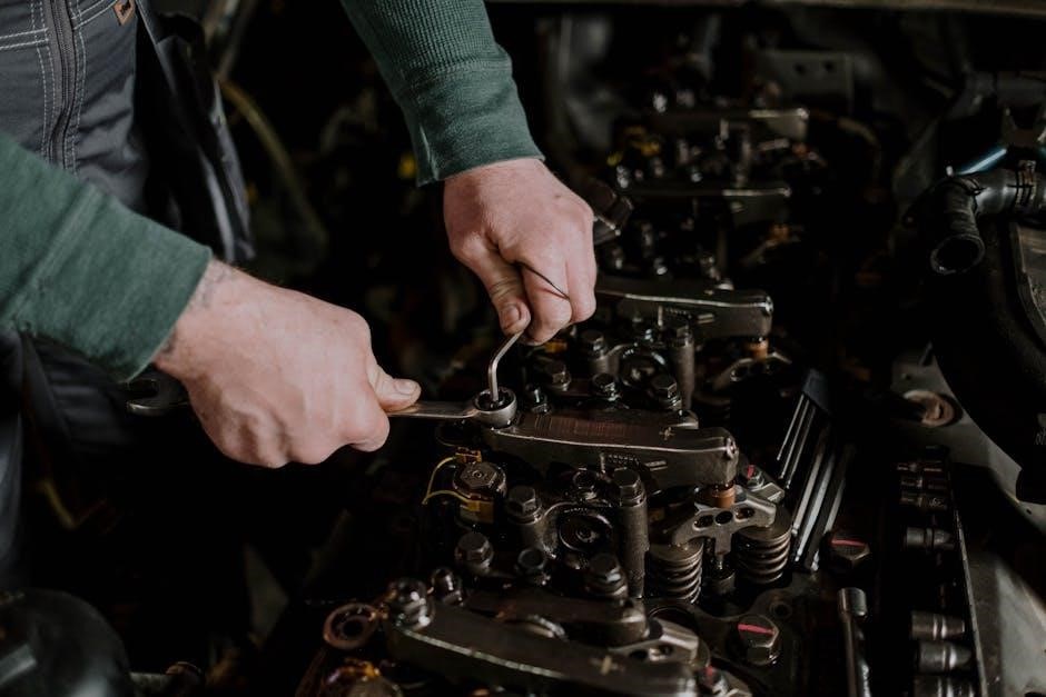
VII. Cylinder Maintenance & Overhaul
Cylinder maintenance is paramount for Lycoming O-360 reliability, focusing on preventative measures and timely overhaul. Regular inspections involve checking for cracks, particularly around the valve seats and spark plug threads, utilizing dye penetrant inspection methods. Valve guide wear is a common issue, necessitating periodic replacement to maintain proper valve alignment and sealing.
Overhaul involves complete disassembly, cleaning, and inspection of all components. Cylinder barrels are inspected for wear and damage, often requiring honing or replacement. Valves are meticulously examined for burning, pitting, and proper seating. New valve guides, springs, and keepers are typically installed during overhaul.
Proper torqueing of all fasteners is critical, adhering strictly to Lycoming’s specifications. Following overhaul, cylinders undergo leak testing to ensure a tight seal. Maintaining cylinder head temperatures within recommended limits, as detailed in the operation manual, extends service life and prevents premature failure.
VIII. Cylinder Inspection Techniques
Thorough cylinder inspection is crucial for identifying potential issues before they escalate. Visual inspection should begin with a careful examination for any signs of cracking, particularly around the valve seats, spark plug bosses, and fin areas. Dye penetrant inspection is essential for detecting hairline cracks invisible to the naked eye, revealing structural weaknesses.
Borescope inspection allows for internal examination of the cylinder barrel, checking for wear, scoring, and carbon buildup. Valve guide wear is assessed by measuring valve stem-to-guide clearance; excessive play indicates the need for replacement. Valve face runout is checked to ensure proper sealing against the valve seat.
Cylinder compression tests provide valuable insight into the sealing efficiency of the valves and piston rings. Leakage past the valves suggests valve seat damage or valve wear. Monitoring cylinder head temperatures (CHT) during operation, as outlined in the operating manual, helps identify cylinders running hotter than others, indicating potential problems.
IX. Valve Inspection and Replacement
Valve inspection is a critical component of Lycoming O-360 maintenance, ensuring optimal engine performance and preventing catastrophic failure. Begin by visually inspecting valves for signs of burning, pitting, or cracking, particularly around the valve face and margins. Check valve stems for straightness and wear, utilizing a precision measuring tool.
Valve spring testing is essential; springs should meet specified length and load requirements. Replace any springs that are cracked, broken, or outside of tolerance. Valve guide replacement is necessary if excessive valve stem-to-guide clearance is detected during inspection. Proper valve seat cutting is vital for achieving a tight seal.
When replacing valves, always use the correct valve type for the specific cylinder and engine model. Lapping valves to their seats ensures a proper mating surface. Following the manufacturer’s recommended procedures for valve installation and torque specifications is paramount for reliable operation and longevity.
X. Piston and Connecting Rod Maintenance
Maintaining pistons and connecting rods is crucial for Lycoming O-360 engine reliability. Regular inspection focuses on identifying wear, damage, and potential failure points. Begin by visually inspecting pistons for scoring, cracks, or excessive carbon buildup. Examine piston skirts for wear and taper, utilizing precision measuring tools to determine if replacement is necessary.
Connecting rod inspection involves checking for bending, twisting, and cracks, particularly around the big end and small end bearings. Measure connecting rod bearing bore diameter and out-of-roundness. Replace connecting rods if they exceed wear limits or show signs of damage.
Proper piston ring installation is vital for maintaining compression. Ensure rings are correctly oriented and seated in their grooves. Always use new piston rings during an overhaul. Following the manufacturer’s torque specifications for connecting rod bolts is paramount to prevent failure and ensure proper engine operation.
XI. Piston Inspection and Measurement
Thorough piston inspection is paramount during Lycoming O-360 maintenance. Begin with a visual check for scoring, cracks – especially near the wrist pin bore – and excessive carbon deposits. Pay close attention to the piston skirt for signs of wear, taper, or damage. Utilize a dial indicator to measure skirt diameter at multiple points, comparing readings to Lycoming’s service limits.
Accurate measurement is key. Measure piston diameter at various locations, noting any ovality or out-of-round conditions. Check piston height relative to the deck surface, ensuring it falls within specified tolerances. Inspect the ring grooves for wear, damage, or carbon buildup that could impede ring function.
Carefully examine the piston crown for evidence of detonation or pre-ignition. Any piston exhibiting excessive wear, damage, or measurements outside of acceptable limits must be replaced. Proper documentation of all measurements is essential for maintaining a comprehensive maintenance record.
XII. Connecting Rod Inspection and Balancing
Connecting rod integrity is crucial for Lycoming O-360 engine reliability. Begin with a meticulous visual inspection for cracks, particularly around the big end and small end bearings, and at any points of stress concentration. Magnetic particle inspection (MPI) is highly recommended to detect subtle cracks not visible to the naked eye.

Check for elongation by comparing the big end diameter to the small end diameter; excessive difference indicates distortion. Ensure the connecting rod is straight using a precision straightedge. Inspect the rod bearing bores for roundness and taper, utilizing precision measuring tools.
Balancing connecting rods is vital for smooth engine operation. Weigh each rod assembly (including bearings) and address any imbalance by removing material from the heavier rod. Dynamic balancing, performed by a specialized shop, is preferred for optimal results. Accurate documentation of weights and balancing adjustments is essential for maintaining a detailed maintenance log.
XIII. Crankshaft and Bearing Maintenance
The Lycoming O-360 crankshaft demands rigorous inspection and maintenance. Begin with a thorough visual check for cracks, especially at fillets, journal surfaces, and counterweight attachments. Dye penetrant inspection is crucial for detecting surface cracks, while magnetic particle inspection (MPI) reveals subsurface flaws. Any identified cracks necessitate crankshaft replacement.
Journal surfaces must be examined for wear, scoring, and galling. Measure journal diameters accurately and compare them to Lycoming’s service limits. If within limits, polishing may be sufficient; otherwise, grinding to the next undersize is required, necessitating the use of undersize bearings.
Bearing inspection involves checking for wear patterns, discoloration, and embedded debris. Proper bearing clearance is critical; measure using Plastigage or a similar method. Replace bearings whenever crankshaft grinding is performed or if any signs of damage are present. Accurate installation, with proper lubrication, is paramount for bearing longevity.

XIV. Crankshaft Inspection for Cracks and Wear
Detailed crankshaft inspection is paramount for Lycoming O-360 reliability. Begin with a meticulous visual examination, focusing on high-stress areas like journal fillets, counterweight junctions, and the rear main journal. Look for any indications of cracking, pitting, or unusual wear patterns. Employing a magnifying glass aids in identifying subtle flaws.
Non-destructive testing (NDT) is essential. Dye penetrant inspection effectively reveals surface cracks, while magnetic particle inspection (MPI) detects subsurface defects. These methods should be performed by certified personnel following established procedures. Any confirmed crack warrants immediate crankshaft replacement – do not attempt repairs.
Wear assessment requires precise measurements. Utilize a micrometer to determine journal diameters at multiple points, comparing readings to Lycoming’s published service limits. Excessive wear, scoring, or out-of-roundness indicates the need for crankshaft grinding or replacement. Careful documentation of all measurements is crucial for tracking wear trends.
XV. Bearing Inspection and Replacement Procedures
Thorough bearing inspection is critical during Lycoming O-360 maintenance. Upon disassembly, carefully examine each bearing for signs of wear, discoloration, or damage. Look for pitting, spalling, or scoring on the bearing surfaces. Feel for roughness or looseness when rotating the bearing within its housing.
Proper replacement procedures are essential for longevity. Always replace bearings in sets – never mix old and new components. Before installation, ensure the crankshaft journals and bearing housings are clean and free of debris. Lubricate the bearings generously with engine oil during assembly.
Torque specifications must be strictly adhered to. Use a calibrated torque wrench to tighten bearing caps to the manufacturer’s recommended values. Incorrect torque can lead to premature bearing failure. After installation, verify crankshaft rotation is smooth and free of binding. Document all bearing clearances and replacement details.
XVI. Magneto Maintenance and Timing
Regular magneto maintenance is vital for reliable ignition in the Lycoming O-360. Inspections should include checking points, condensers, rotors, and wiring for wear, corrosion, or damage. Clean all components thoroughly with approved solvent, ensuring no residue remains.
Proper timing is crucial for optimal engine performance. Utilize a timing light to verify ignition timing for each magneto independently, referencing the engine manufacturer’s specifications. Adjust timing as needed, ensuring both magnetos fire at the correct moment.
Dynamic and static timing checks are both necessary. Dynamic timing is performed while the engine is running, while static timing is checked with the engine stopped. Pay close attention to impulse coupling operation. Document all timing adjustments and magneto inspection findings. Replace any questionable components to maintain ignition system integrity.
XVII. Magneto Inspection and Cleaning
Thorough inspection of the magnetos is paramount during Lycoming O-360 maintenance. Begin with a visual check for cracks, corrosion, and loose connections on the magneto housing, terminals, and wiring harness. Carefully examine the points for pitting, burning, or improper gap settings. Inspect condensers for swelling or leakage, as these can cause intermittent ignition failures.
Cleaning is essential for reliable operation. Disassemble the magneto, carefully noting the position of all parts. Use an approved solvent to remove dirt, oil, and carbon buildup from all components. Avoid abrasive cleaners that could damage precision surfaces. Pay particular attention to the points and distributor block, ensuring they are free of contaminants.
After cleaning, inspect all parts again for wear or damage. Replace any components that do not meet service limits. Reassemble the magneto, ensuring proper lubrication and correct point gap settings. Verify the free movement of all moving parts before reinstalling the unit on the engine.
XVIII. Ignition Timing Procedures
Precise ignition timing is critical for optimal Lycoming O-360 performance and preventing engine damage. Begin by ensuring the engine is at Top Dead Center (TDC) on the compression stroke of cylinder number one. Utilize a timing window or appropriate inspection plate to visually confirm TDC.
Connect a timing light to the magneto being timed. Slowly advance the timing while observing the timing marks on the flywheel or crankshaft damper. Refer to the engine’s specifications for the correct static timing setting – typically around 25 degrees Before Top Dead Center (BTDC).
Adjust the magneto base to achieve the specified timing. Tighten the mounting screws securely after adjustment; Repeat the process for the second magneto, ensuring both are synchronized. Verify timing accuracy by bumping the starter and observing the timing light. Fine-tune as needed. Improper timing can lead to detonation, reduced power, and increased wear.
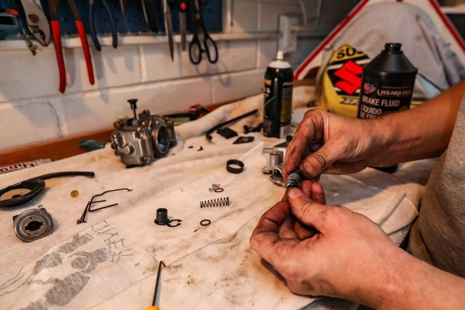
XIX. Carburetor Maintenance and Adjustment
Regular carburetor maintenance is essential for consistent fuel delivery and smooth engine operation in the Lycoming O-360. Begin by thoroughly inspecting all fuel lines, connections, and the carburetor body for leaks or damage. Disassemble the carburetor, carefully noting the position of all components.
Clean all passages and jets with carburetor cleaner, ensuring they are free of obstructions. Pay close attention to the float and needle valve, checking for wear or damage. Inspect the throttle and mixture control linkages for smooth operation and proper adjustment.
Reassemble the carburetor with new gaskets and seals. Adjust the idle mixture and idle speed according to the engine manufacturer’s specifications. Verify proper operation by running the engine and observing the response to throttle and mixture control adjustments. A poorly maintained or adjusted carburetor can cause rough running, poor fuel economy, and potential engine failure.
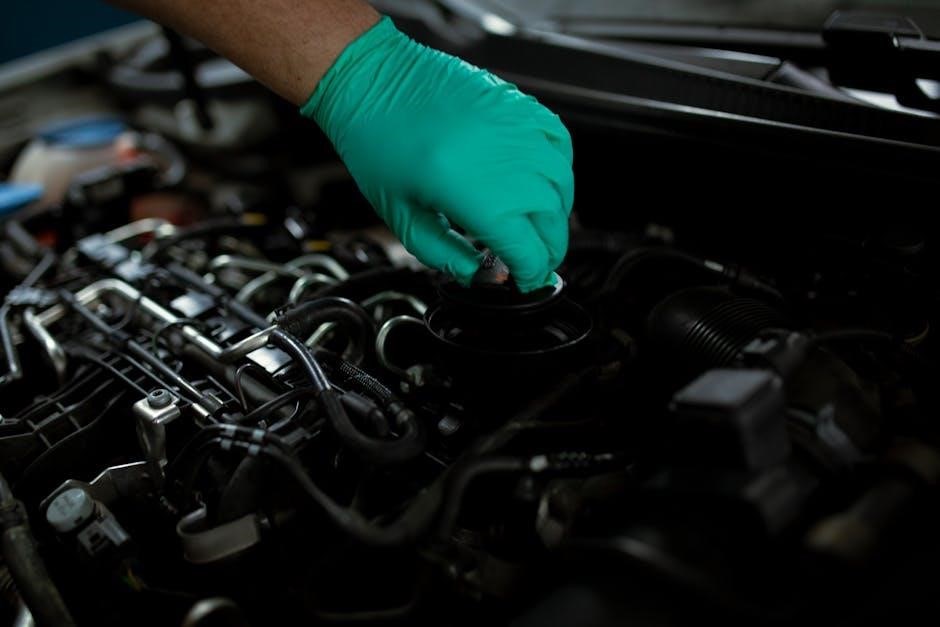
XX. Oil System Maintenance

Maintaining a clean and efficient oil system is paramount for Lycoming O-360 engine longevity. This involves regular oil and filter changes, alongside thorough inspections of all oil system components. Begin by checking the oil level and condition before each flight, looking for any signs of contamination or unusual appearance.

During scheduled maintenance, replace the oil filter according to the manufacturer’s recommendations. Perform an oil analysis to detect any metal particles or fuel dilution, indicating potential internal engine wear. Inspect oil lines, connections, and the oil cooler for leaks or damage.
Verify proper oil pressure using a calibrated gauge. Check the operation of the oil pump and pressure relief valve. A compromised oil system can lead to inadequate lubrication, accelerated wear, and catastrophic engine failure. Consistent oil system maintenance is a critical investment in engine reliability and performance.
XXI. Oil Filter Replacement and Analysis
Routine oil filter replacement is a cornerstone of Lycoming O-360 maintenance. Utilize an approved filter, ensuring a proper seal to prevent oil leakage. Before removal, note the filter’s condition – excessive debris suggests internal engine issues. During installation, lightly lubricate the gasket with clean oil for a secure fit.
Oil analysis provides invaluable insights into engine health. Send a sample to a qualified laboratory for a comprehensive report. This analysis identifies wear metals (iron, aluminum, copper), fuel dilution, coolant leaks, and oil degradation. Trending oil analysis results reveals patterns, allowing for proactive maintenance before significant problems arise.
Interpreting the report requires understanding the acceptable limits for each parameter. Elevated wear metal levels indicate component wear, while fuel dilution reduces oil’s lubricating properties. Regular oil filter replacement coupled with consistent oil analysis is a proactive approach to maximizing engine life and minimizing unexpected downtime.